
 English
 中文简体
 Español
 Português

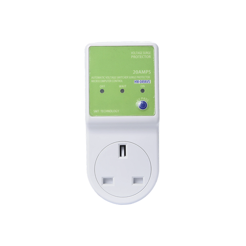
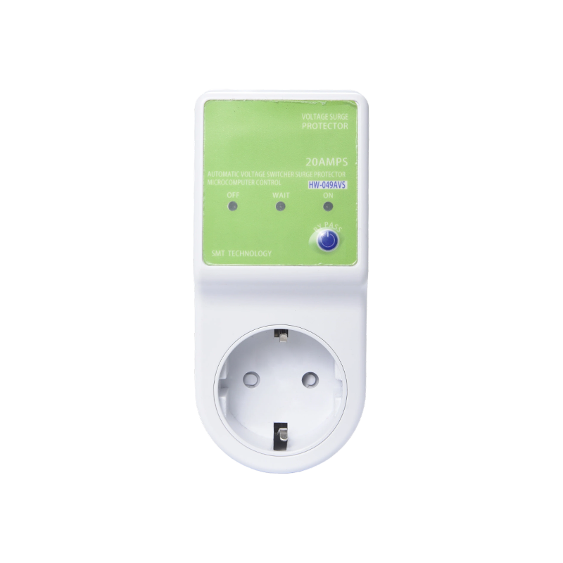
With the continuous increase of electrical safety supervision, the certification system of the over/under voltage protector smart socket industry is ...
READ MORE
Industry News
Home / News / Industry News / Construction of Over and Under Voltage Circuit Protector: Sensing and Switching Design
Construction of Over and Under Voltage Circuit Protector: Sensing and Switching Design
Update:08-10-2026
What sits between the socket and the appliance: sensing, reference, comparison, delay and switching, and how those choices decide whether a protector survives real loads.
A 230 V line that sags to 170 V on a hot afternoon will stall a compressor and overheat its winding within minutes. The protector plugged in ahead of that air conditioner is expected to disconnect quickly, stay disconnected, and reconnect only once the line has settled. That behaviour does not come from one chip; it comes from a set of stages that must work together, each with its own tolerance, its own cost and its own failure mode.
The conclusion first: reliability is decided by four things. How accurately the sensing reference measures the line, how wide the trip window is and how much hysteresis it carries, how long the reconnection delay lasts, and how the switching element and the load path around it are sized. The enclosure and plug format follow, because they decide which markets the unit can enter.
Two protectors can share the same housing, the same rating on the label and a tenfold price gap. What separates them is almost never the plastic.
The Four Stages Inside a Voltage Protector
Strip the housing off a modern over and under voltage protector and the same functional chain appears, whether the unit plugs into a single socket or mounts on a DIN rail.
- Sensing and reference: scales the mains down and produces a stable DC reference against which the line is measured.
- Comparison: decides whether the measured value sits inside or outside the acceptable window, with hysteresis to stop chatter at the edges.
- Delay and logic: holds the output off after a fault and re-arms only after a continuous healthy period.
- Switching and load path: the relay or contactor contacts, the PCB copper, the terminals, and the small internal supply that feeds the electronics.
Most field failures trace back to a mismatch between stages: an accurate sensing circuit paired with a relay too small for the load, or a well-sized relay paired with a reference that drifts as the board warms. Readers who want the detection side explained in depth can start with this guide to voltage protector working principles and types; the rest of this article stays on construction.
Sensing, Reference and Where Accuracy Comes From
Two sensing techniques dominate. A resistive divider scales 230 V down to a few volts before rectification and smoothing. It is compact and inexpensive, but its accuracy follows resistor tolerance and drifts as the components warm. A small transformer or an isolated measurement path costs more board space and copper, yet it holds accuracy better and survives transients that would saturate a simple divider.
The signal then has to be converted into something the comparator can judge. Peak detection reacts quickly but misreads distorted waveforms; RMS conversion is slower but tracks the true heating effect of the supply. On grids carrying heavy inverter or motor load, that difference decides between nuisance tripping and stable operation.
Typical window settings
On a 230 V nominal supply, factory settings usually land near 175 V for the under-voltage trip and 250 V for the over-voltage trip, with reconnection delayed by minutes. Adjustable models move the under-voltage threshold across roughly 150–210 V and the over-voltage threshold across roughly 230–280 V. Accuracy within plus or minus 2% is a reasonable expectation from a properly built unit; a 5% error on the under-voltage side means a compressor can already be starved before the relay opens.
The Delay Stage and What It Protects
The delay stage is what turns a switch into a protector. When the line returns to a healthy value, the compressor needs time to equalise refrigerant pressure. Reconnecting too early restarts the motor against a loaded system, which shortens its life faster than the voltage event itself.
Construction differences are visible here. Analog designs use an RC network feeding a comparator, with the delay fixed by a capacitor and a resistor. Digital designs run a small microcontroller, which allows market-specific delay profiles and turns factory calibration into a software step instead of a soldering step. Both are workable. The questions worth asking are how the delay behaves when the supply flickers repeatedly, and whether reconnection requires a continuous healthy period rather than a single clean sample.
A protector that reconnects ten seconds after the voltage returns looks like it is working, because the appliance starts. The cost appears months later as a failed compressor, and it is not covered by the protector's warranty.
Choosing the Switching Element
The switching stage carries the entire load, and it is usually the first part to fail when a design is under-specified.
- PCB-mount relay: compact and inexpensive, suited to 10–16 A resistive loads. Welded contacts are the classic failure once inductive or high-inrush loads are switched repeatedly.
- Heavy-duty relay or small contactor: wider contact gaps and silver alloy tips, used in 30 A designs and in units intended for air conditioners.
- Triac or solid-state switch: silent and unlimited in switching cycles, but it produces heat that must be dissipated and generally costs more per ampere.
A label rating describes steady current. A compressor draws several times that figure for a fraction of a second at start-up, so a relay chosen on the label figure alone will not last. A 120 V 30 A automatic voltage surge protector built for the North American market is a useful reference point when comparing how suppliers size contacts for the same nominal rating.
The Load Path and Its Thermal Budget
Between the relay and the socket sits the load path: copper traces, solder joints, terminal screws and internal wiring. Its quality shows up as heat and voltage drop. At 230 V, a 3300 W rating corresponds to roughly 14.3 A, so a 15 A design carries barely 5% of headroom. That margin holds only if trace width, copper weight and terminal torque are all controlled in production.
A 230 V, 15 A, 3300 W adjustable unit is a representative example of how that thermal budget gets packaged for a high-draw appliance such as an air conditioner or a water heater.
Surge handling is built separately. Metal oxide varistors absorb short spikes and are chosen by clamping voltage and energy rating; they do not disconnect an appliance from a sustained over-voltage. A protector claiming both functions should contain both sets of parts.
Housing, Plug Interface and Regional Construction
The housing and plug interface decide which markets a product can legally enter, and they change the electrical construction more than buyers expect. European Schuko plugs are rated 16 A and carry an earth clip on the side; North American NEMA 5-15 plugs are rated 15 A with a different blade geometry. The same electronics therefore sit in different mouldings, with different terminal spacing and creepage distances.
Multi-outlet versions add another constraint. Every socket shares one relay and one set of contacts, so aggregate current matters rather than the current per socket. A 120 V, 15 A multiple outlet automatic voltage surge protection unit shows the point clearly: the housing looks generous, but the switching element still has to carry everything plugged into it.
Plastic selection belongs to construction as well. Flame-retardant grades rated UL94 V-0, adequate wall thickness around live parts, and recessed or shuttered sockets where local rules demand them all affect cost and safety far more than surface finish does.
Verification: What to Measure Instead of Look At
Because most of the construction is invisible from outside, incoming inspection has to rely on measurements. The checks below separate a compliant shipment from a problematic one more reliably than any visual inspection.
| Check | Typical expectation | Why it matters |
|---|---|---|
| Trip accuracy | Within plus or minus 2% of the set point | A 5% error can let the load run in a damaging range |
| Reconnection delay | 180 seconds typical; 300 seconds for compressor loads | Prevents short cycling of motors |
| Contact rating | At least 1.25 times the continuous load current | Undersized contacts weld and overheat |
| Voltage drop at rated current | Below 1% across the unit | Heat, wasted energy and nuisance shutdowns |
| Dielectric strength | 1.5 to 2 kV for one minute between live parts and touchable surfaces | Directly affects user safety |
| Endurance | 10,000 operations at rated load or better | Unstable grids cycle the relay constantly |
A supplier who can show batch-level records for trip accuracy and dielectric strength removes most of the uncertainty from the purchase, because those two tests cover the sensing stage and the safety barrier at the same time.
Turning Construction Choices Into an Order Specification
For importers and brand owners, everything above becomes a specification sheet. The more precisely it is written, the less room there is for substitution during production.
- Nominal voltage, frequency and plug standard for the destination market.
- Trip window, adjustment range and hysteresis, stated as numbers with tolerances.
- Reconnection delay, including behaviour during repeated flicker.
- Continuous current rating, load type and starting current of the target appliance.
- Certification evidence, covering both the facility and the product batch.
- Label artwork, packaging, plug moulding and market-specific safety features.
A manufacturer that designs its own boards and moulds can adjust all six without rebuilding the platform from scratch, which is what makes OEM and ODM work practical rather than theoretical. Haowei Electric, for instance, builds EU-standard and US-standard voltage protectors from one in-house design team, and its catalogue of voltage protectors shows the same functional platform stretched across 110 V, 120 V and 230 V markets and 5 A to 30 A current classes.
The construction of an over and under voltage circuit protector is not exotic, but it is unforgiving. Sensing decides what the unit notices, the window and hysteresis decide when it acts, the delay decides whether the appliance survives the recovery, and the switching stage together with the load path decides whether the protector itself is still working next season. When one quotation looks unusually cheap for the same nominal rating, the difference almost always sits in one of those four places.
If only three numbers can be requested from a supplier, ask for trip accuracy, reconnection delay and continuous contact rating at the stated load. Those three explain most of the price gap between two protectors wearing the same label.
Recommended Products
News
-
-
With the improvement of residents' awareness of electrical safety and the rapid development of the smart home market, over/under voltage protector sm...
READ MORE -
With the improvement of residents' living quality and the enhancement of awareness of electrical safety, consumers' demand for over/under voltage pro...
READ MORE -
According to industry research data, the global over/under voltage protection module market scale is growing steadily, and it is expected to increase...
READ MORE -
Voltage Spike Protector Outlet: What It Is, Key Specs, and How to Choose Behind many appliance failures is not a dramatic lightning strike but a bri...
READ MORE -
Surge Arrester and Over/Under Voltage Protection Surge Arresters and Over/Under Voltage Protectors Are Not the Same Device One deflects lightning-sc...
READ MORE

Ningbo Haowei Electric Technology Co., Ltd.
-
Address
No. 261 Lvyuan 2nd Road, Chongshou Town, Qianwan New Area, Ningbo City, Zhejiang Province, China
-
Mobile
+86-13566611998
-
Email
Copyright © Ningbo Haowei Electric Technology Co., Ltd. Rights Reserved.
 Custom Smart Timer Plug Manufacturers